Phase Camera 1: TCS Calibration Shift 15 Jan 09
Page 1 of 1
 Phase Camera 1: TCS Calibration Shift 15 Jan 09
The goal of this shift was to try and centre the central spot and then the ring on the input mirrors.
We tried to visualize the central spot as we had done previously for the west arm. In the same time we have done measurement on the WI with the ring C02.
We conserved the same TCS mirror B position from the Tuesday shift (21706) when we centred the central spot.
Up_Left = 6200, Bottom_Left = -300, Bottom_Right = 300
We switched on the CO2 ring with 14 W of power.
We kept the annulus switched on for just two minutes in order to avoid long transients slowing down the calibration process.

We moved the Mirror in order to better the center of Ring.

As the WI mirror has been heated alot we decide to switch back to the
North arm for which the TCS bench has finished being aligned.
We switch on the central spot to the power of 144 mW. We move the TCS
mirror B to centre the blue spot in the phase image. Fig 3 shows the
phase image of the centred central spot. the TCS mirror position is:
Up_Left = 451, Bottom_Left = 200, Bottom_Right = 4025
We switched off the central spot and switched on the CO2 ring with 12 W
of power. Fig 4 shows the resulting phase image. As with the West arm
we see a blue spot close to the central spot position. We again tried
moving the TCS mirror to various different positions and again, as with
the West arm, found a position for which we have a phase image
corresponding to the negative lens at the centre of the input mirror
(fig 5). The TCS mirror position is: Up_Left = 1151, Bottom_Left = 200,
Bottom_Right = 5025.
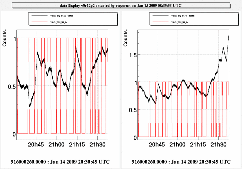
We then tried moving the ring around this position. As the TCS power
was very large we saw that the cavity became very sensitive to the
alignment of the ring. It would seem that the misaligned ring causes
the beam to be deviated. This was observed on V1:Gx_B7p_PosX_TIME and
V1:Gx_B7p_PosY_TIME. In fig 6 we see the position changing while we
move the ring.
Conclusion:
Both West arm and North had extremely similar behaviour for all aspects of the test.
We have located easily the position of the central spot using the phase
camera for both arms. However the phase camera image when using the CO2
ring is not easy to understand. We are still not sure of the alignment
of the ring for both North and West arm.
Fig3:

Fig4:

Fig5:

Fig6:

We tried to visualize the central spot as we had done previously for the west arm. In the same time we have done measurement on the WI with the ring C02.
We conserved the same TCS mirror B position from the Tuesday shift (21706) when we centred the central spot.
Up_Left = 6200, Bottom_Left = -300, Bottom_Right = 300
We switched on the CO2 ring with 14 W of power.
We kept the annulus switched on for just two minutes in order to avoid long transients slowing down the calibration process.

We moved the Mirror in order to better the center of Ring.

As the WI mirror has been heated alot we decide to switch back to the
North arm for which the TCS bench has finished being aligned.
We switch on the central spot to the power of 144 mW. We move the TCS
mirror B to centre the blue spot in the phase image. Fig 3 shows the
phase image of the centred central spot. the TCS mirror position is:
Up_Left = 451, Bottom_Left = 200, Bottom_Right = 4025
We switched off the central spot and switched on the CO2 ring with 12 W
of power. Fig 4 shows the resulting phase image. As with the West arm
we see a blue spot close to the central spot position. We again tried
moving the TCS mirror to various different positions and again, as with
the West arm, found a position for which we have a phase image
corresponding to the negative lens at the centre of the input mirror
(fig 5). The TCS mirror position is: Up_Left = 1151, Bottom_Left = 200,
Bottom_Right = 5025.
We then tried moving the ring around this position. As the TCS power
was very large we saw that the cavity became very sensitive to the
alignment of the ring. It would seem that the misaligned ring causes
the beam to be deviated. This was observed on V1:Gx_B7p_PosX_TIME and
V1:Gx_B7p_PosY_TIME. In fig 6 we see the position changing while we
move the ring.
Conclusion:
Both West arm and North had extremely similar behaviour for all aspects of the test.
We have located easily the position of the central spot using the phase
camera for both arms. However the phase camera image when using the CO2
ring is not easy to understand. We are still not sure of the alignment
of the ring for both North and West arm.
Fig3:

Fig4:

Fig5:

Fig6:

mdipaolo- Posts : 106
Join date : 2008-11-05
 Similar topics
» Phase Camera 1: Ring Alignment Shift 19 Jan 09
» Phase Camera 1: Ring Aligment NI Shift 20 Jan 09
» Phase Camera 1: Ring Aligment WI Shift 26 Jan 09
» Phase Camera 1: Calibration of the Ring WI Shif 16 Jan 09
» Phase Camera
» Phase Camera 1: Ring Aligment NI Shift 20 Jan 09
» Phase Camera 1: Ring Aligment WI Shift 26 Jan 09
» Phase Camera 1: Calibration of the Ring WI Shif 16 Jan 09
» Phase Camera
Page 1 of 1
Permissions in this forum:
You cannot reply to topics in this forum|
|
|
