Phase Camera 1: Ring Aligment WI Shift 26 Jan 09
Page 1 of 1

Phase Camera 1: Ring Aligment WI Shift 26 Jan 09
![]() Alessio Tue Jan 27, 2009 7:29 pm
Alessio Tue Jan 27, 2009 7:29 pm
Log book entry evening shift 26Jan2009
The goal of this shift was to try to check the centering of the two CO2 rings.
Before starting this shift previous results showed current CO2 ring centred positions for TCS mirrors are
NI UL = -1399
NI BR = 2675
NI BL = 200 (not to be touched)
WI UL = 5900
WI BR = 1200
WI BL = -300 (not to be touched)
OMC temperature set to 22.72 degrees
A calibration check of ring powers was made since observations made of the etalon effect.
Fig 1 and 2 shows the new calibration of North and West respectively.
The calibration has is almost the same as previously measured.
North arm
---------------
Problems of drift of B7p due to something being heated by PR misaligned to -10000 microrad.
PR misaligned by -1000 microradians. This seemed to stop the B7p drift while retaining a good quality phase camera image.
Baseline taken and used at 20h47.
NI CO2 ring Power set to 12 W
*NI ring shutter switched on at Time: Jan26,09-21:53:18 > GPS: 917038413
The image does not look like the round negative lens we were expecting (Fig 3)
B7p positions started drifting dramatically (Fig 4) so we had to switch off ring.
*NI ring shutter switched off at Time: Jan26,09-21:57:24 > GPS: 917038659
The B7p drift suggests that we are very mis-centred.
We would like to see if we can centre the ring using the B7p signal.
First we position the motors to where the central spot should be.
-NI UL = 451, NI BL = 200, BR = 4025
Central spot set to 135mW
*NI Central spot shutter switched on at Time: Jan26,09-22:36:17 > GPS: 917040992
-NI UL 451 to 951 at Time: Jan26,09-22:42:31 > GPS: 917041366
-NI UL 951 to 1451 at Time: Jan26,09-22:45:31 > GPS: 917041546
-NI UL 1451 to 701 at Time: Jan26,09-22:50:47 > GPS: 917041862
We see clearly the effect of the central spot on the B7p beam confirming what we observe with the phase camera (Fig 5).
Sudden unlock of cavity due to removal of tidal control.
*NI Central spot shutter switched off Time: Jan26,09-23:01:22 > GPS: 917042497
Relock without tidal control but lock is too unstable to continue.
We left the shift with interferometer locked at step 12.
Conclusion:
Problem of input beam alignment due to PR position -10000 microrad heating some unknown component.
It is noted that B7p and B8p position signals are very sensitive to thermal lens centering and could be used for intitial CO2 beam alignments.
It is doubtful that the North ring is centred correct. we must continue with this test using B7p as soon as possible.

Alessio- Posts : 127
Join date : 2008-11-07
Age : 52
Location : Rome
TCS power calibration
![]() Alessio Tue Jan 27, 2009 7:31 pm
Alessio Tue Jan 27, 2009 7:31 pm
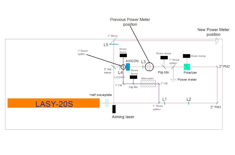
The main difference between the two calibrations is that we changed the position of the power meter that measures the CO2 power that goes on the ITMs.
Looking at the attached layout of the benches, it is possible to notice that in the old measurements, the power meter was placed between the flip mirror and L3. This was fine since it was possible to neglect the power absorbed or back-reflected by the following optics, since they are all treated with AR coating, untill the CH telescope was installed.
When we installed the CH telescope, after the AXICON a 10% reflecting beam splitter was inserted. So the old calibration did not take into account this amount of power reflected towards the beam dump.
Yesterday night, with Richard, we placed the power meter at the very end of the telescope. So the new calibration now takes into account all the optics, except, off course, the ZnSe viewport on the tower.
Alessio- Posts : 127
Join date : 2008-11-07
Age : 52
Location : Rome
» Phase Camera 1: Ring Aligment NI Shift 20 Jan 09
» Phase Camera 1: Ring Alignment Shift 19 Jan 09
» Phase Camera 1: TCS Calibration Shift 15 Jan 09
» Phase Camera 1: Calibration of the Ring WI Shif 16 Jan 09
» Phase Camera
» Phase Camera 1: Ring Alignment Shift 19 Jan 09
» Phase Camera 1: TCS Calibration Shift 15 Jan 09
» Phase Camera 1: Calibration of the Ring WI Shif 16 Jan 09
» Phase Camera
Page 1 of 1
Permissions in this forum:
You cannot reply to topics in this forum|
|
|