Compensation Plate performances
Page 1 of 1

Compensation Plate performances
![]() Alessio Fri Jan 09, 2009 2:43 pm
Alessio Fri Jan 09, 2009 2:43 pm
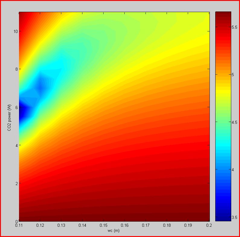
I analized the performances of the correction due to CP, as usual in terms of coupling losses. I applied a heating profile à la Vinet shown in the next figure
The analitycal expression is in the form
I(r)=cosh(r2/wc2)-exp(-2*r2/w2)
wc is a parameter that I changed ranging from 0.11m to 0.2m, while I kept w costant at the value of 0.06m, the same as the waist of the heating pattern on the TM. In this preliminary analisys I neglected the heat exchange btw TM and CP due to radiation (as if CP and TM are far apart). Moreover, there is no ring heater around the TM to correct the ROC.
The first figure shows the Log of the coupling losses as a function of wc and the CO2 power for a CP that is 0.065m thick.
The second image is the same calculation, but using a profile given by an AXICON. In this case wc represents the Inner Radius of the ring, the outer radius being fixed at 0.13m.

We can see that in both cases it is possible to achieve coupling losses of the order of 104 ppm.
The analitycal expression is in the form
I(r)=cosh(r2/wc2)-exp(-2*r2/w2)
wc is a parameter that I changed ranging from 0.11m to 0.2m, while I kept w costant at the value of 0.06m, the same as the waist of the heating pattern on the TM. In this preliminary analisys I neglected the heat exchange btw TM and CP due to radiation (as if CP and TM are far apart). Moreover, there is no ring heater around the TM to correct the ROC.
The first figure shows the Log of the coupling losses as a function of wc and the CO2 power for a CP that is 0.065m thick.
The second image is the same calculation, but using a profile given by an AXICON. In this case wc represents the Inner Radius of the ring, the outer radius being fixed at 0.13m.
We can see that in both cases it is possible to achieve coupling losses of the order of 104 ppm.
Last edited by Alessio on Thu Feb 12, 2009 9:29 pm; edited 2 times in total (Reason for editing : Figure sbagliate)

Alessio- Posts : 127
Join date : 2008-11-07
Age : 52
Location : Rome
Radiative heat exchange btw CP and TM on
![]() Alessio Fri Jan 09, 2009 2:52 pm
Alessio Fri Jan 09, 2009 2:52 pm
I repeated the analysis in the case of an AXICON profile with the complete TCS set-up: TM+CP+RH. The ring heater is placed in the position that minimizes the power to correct ROC errors and is emitting circa 15W in all directions. The distance btw CP and TM is 1cm and the CP is 0.065m thick. Results are shown in the next figure as usual.
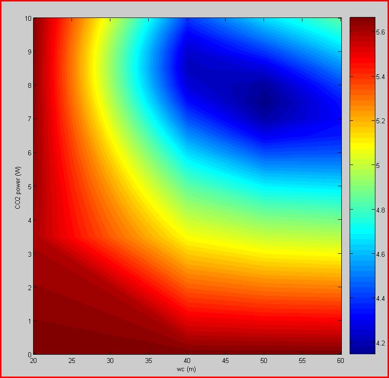
The results do not differ very much from those found when the RH is not present, meaning that it's contribution is rather negligible. Again the best coupling losses is in the 104ppm region. It may be worth increasing the outer radius of the annular pattern to 0.14m (next analisys).
The results do not differ very much from those found when the RH is not present, meaning that it's contribution is rather negligible. Again the best coupling losses is in the 104ppm region. It may be worth increasing the outer radius of the annular pattern to 0.14m (next analisys).
Last edited by Alessio on Thu Feb 12, 2009 9:30 pm; edited 2 times in total (Reason for editing : Analisi e figura sbagliate)
Alessio- Posts : 127
Join date : 2008-11-07
Age : 52
Location : Rome
Re: Compensation Plate performances
![]() Alessio Wed Feb 11, 2009 3:30 pm
Alessio Wed Feb 11, 2009 3:30 pm
Alessio wrote:The results do not differ very much from those found when the RH is not present, meaning that it's contribution is rather negligible.
I must correct myself: the ring heater contribution is not negligible, it is correcting the lensing due to the heat radiated from the CP to the TM.
Alessio- Posts : 127
Join date : 2008-11-07
Age : 52
Location : Rome
Increased the outer radius of the AXICON pattern to 0.14m
![]() Alessio Thu Feb 12, 2009 9:34 pm
Alessio Thu Feb 12, 2009 9:34 pm
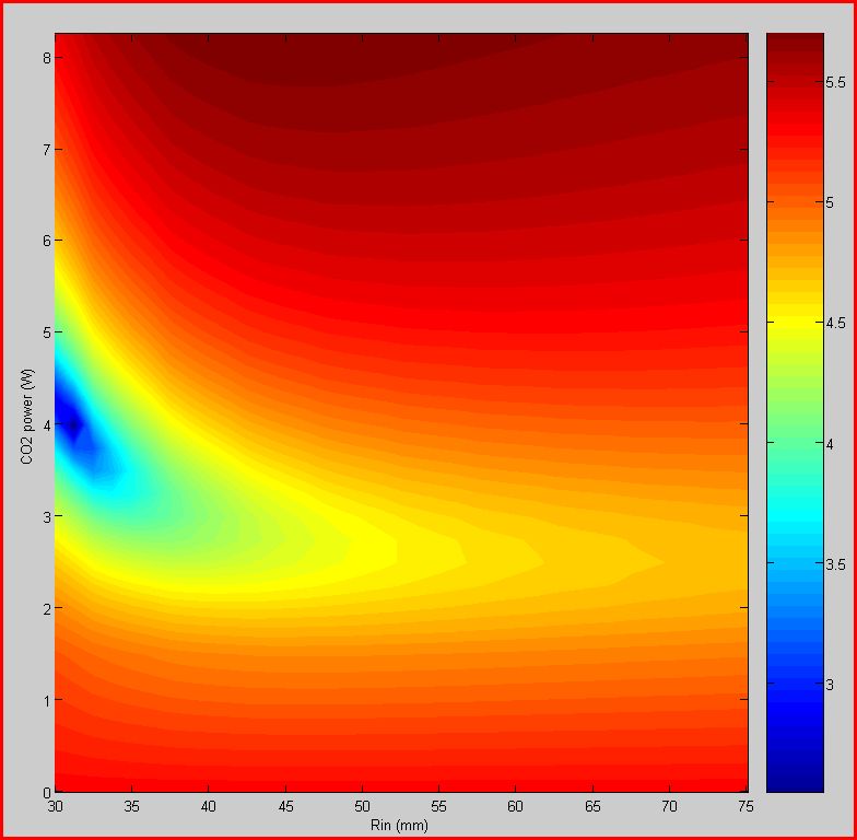
I repeated the analisys of the complete setup with an AXICON pattern, but I increased the outer radius of the profile to 0.14m, so to heat the CP all the way to the edge.
The result is just a little bit better than with Rout=0.13m, still the best coupling losses are around 104ppm. I want to try to increase the radius of the CP to 0.15m...
The result is just a little bit better than with Rout=0.13m, still the best coupling losses are around 104ppm. I want to try to increase the radius of the CP to 0.15m...
Alessio- Posts : 127
Join date : 2008-11-07
Age : 52
Location : Rome
Increased resolution for the case of AXICON pattern with Rout=0.14m
![]() Alessio Fri Feb 13, 2009 5:26 pm
Alessio Fri Feb 13, 2009 5:26 pm
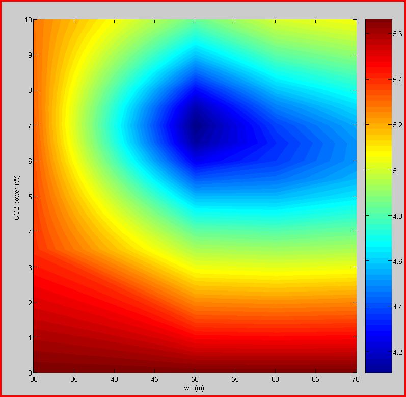
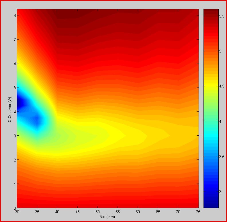
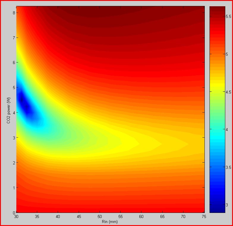
I simply increased the power and Rin resolution. Now the power ranges from 3.5W to 10.25W in steps of 0.25W (before it was 0.5W), while Rin goes from 30mm to 75mm in steps of 5mm (before it was 10mm). Results do not change much. The minimum is for Rin between 40mm and 45mm and P is around 7.0W-7.25W.
Alessio- Posts : 127
Join date : 2008-11-07
Age : 52
Location : Rome
CP far from the TM
![]() Alessio Mon Feb 16, 2009 6:46 pm
Alessio Mon Feb 16, 2009 6:46 pm
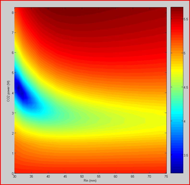
Triggered by Viviana, I tried to see what happens if the CP is far away from the TM (heated by the RH). So, I made the usual simulations (Rin from 35mm to 75mm by 5mm and PCO2 from 3.25W to 10.25W by 0.25W). I analized two cases: CP is 0.065m or 0.1m thick. Here hare the results in the usual form.
CP is 0.065m thick...

... and CP is 0.1m thick
As it is clear from the plot, a thinner CP is better. In the case of the 0.065m CP it is possible to achieve coupling losses as low as 103ppm. We can finally say, by comparing the case of the complete setup and the case of the "far-away" 0.065m CP, that having the CP close to the test mass is increasing coupling losses by a factor of 10.
CP is 0.065m thick...
... and CP is 0.1m thick
As it is clear from the plot, a thinner CP is better. In the case of the 0.065m CP it is possible to achieve coupling losses as low as 103ppm. We can finally say, by comparing the case of the complete setup and the case of the "far-away" 0.065m CP, that having the CP close to the test mass is increasing coupling losses by a factor of 10.
Last edited by Alessio on Tue Feb 24, 2009 7:17 pm; edited 2 times in total
Alessio- Posts : 127
Join date : 2008-11-07
Age : 52
Location : Rome
OPL increase relative to the minima of coupling losses
![]() Alessio Tue Feb 17, 2009 7:04 pm
Alessio Tue Feb 17, 2009 7:04 pm
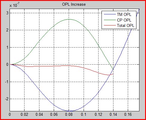
To have an idea of what is happening where we have the minima of the couplig losses, I calculated the related OPL increase.
Figure 1 shows the OPL of the complete setup (RH+TM+CP, CP and TM are close to each other) the corresponding coupling losses are 104ppm, figure 2 show the same quantity for the case of a CP 0.065m thick, far away from the TM, corresponding coupling losses are 1300ppm. Third figure is the same as figure 2, but the CP is 0.1m thick, coupling losses are about 104ppm.
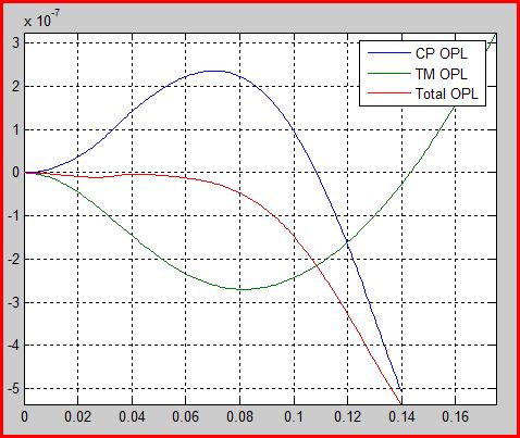
From the figures 2 and 3 it is possible to notice very clearly the contribution of the RH to the TM OPL. On figure 1, the RH contribution is almost negligible, this may be due to the heating of the TM by the radiation from the CP. Since it is clear that a thick CP is worse than a thin CP, the LIGO need for gold coating of the TM barrel could be explained by the fact that their CP is 0.13m thick.
Figure 1 shows the OPL of the complete setup (RH+TM+CP, CP and TM are close to each other) the corresponding coupling losses are 104ppm, figure 2 show the same quantity for the case of a CP 0.065m thick, far away from the TM, corresponding coupling losses are 1300ppm. Third figure is the same as figure 2, but the CP is 0.1m thick, coupling losses are about 104ppm.
From the figures 2 and 3 it is possible to notice very clearly the contribution of the RH to the TM OPL. On figure 1, the RH contribution is almost negligible, this may be due to the heating of the TM by the radiation from the CP. Since it is clear that a thick CP is worse than a thin CP, the LIGO need for gold coating of the TM barrel could be explained by the fact that their CP is 0.13m thick.
Alessio- Posts : 127
Join date : 2008-11-07
Age : 52
Location : Rome
Minimum coupling losses as a function of the CP thickness
![]() Alessio Fri Feb 20, 2009 5:02 pm
Alessio Fri Feb 20, 2009 5:02 pm
In the simulations done with the TM heated by the RH and the CP far away with thicknesses of 0.065m and 0.1m it is clearly visible that coupling losse tend to decrease as the CP thickness decreases. So I wanted to verify this and I made simulations for different CP thicknesses. Each time, I recorded the minimum coupling losses, that occurs for different CO2 powers and profile's inner radius. Figure shows the results.
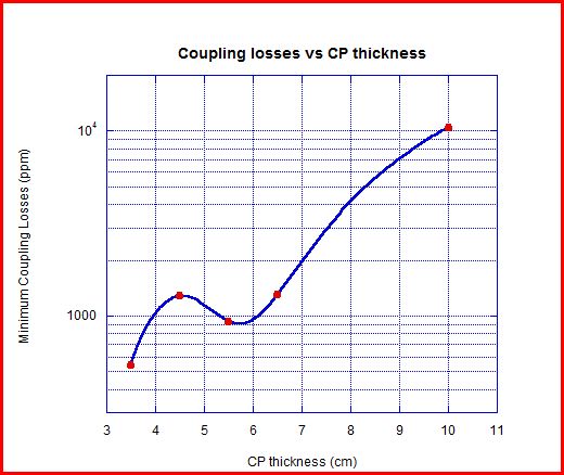
It seems that with a CP 3.5cm thick, it is possible to reach coupling losses as low as 540ppm, astonishing! Next picture shows the usual Log(Losses) vs CO2 power and Rin
It seems that with a CP 3.5cm thick, it is possible to reach coupling losses as low as 540ppm, astonishing! Next picture shows the usual Log(Losses) vs CO2 power and Rin
Last edited by Alessio on Tue Feb 24, 2009 7:18 pm; edited 1 time in total
Alessio- Posts : 127
Join date : 2008-11-07
Age : 52
Location : Rome
CPs and BS
![]() Alessio Fri Feb 20, 2009 5:20 pm
Alessio Fri Feb 20, 2009 5:20 pm
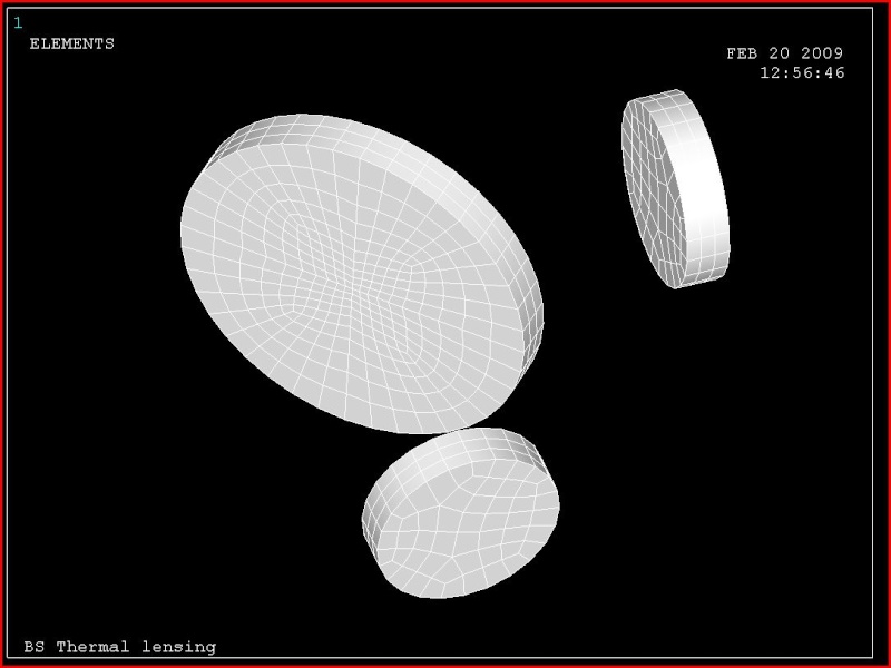
It is now clear to everybody, that putting CPs close to the test mass is making TCS almost ineffective. The question is: where to put them? Our first proposition was to hang them from the BS tower: it was said it is impossible. Now it seems that this "impossibility" has been relaxed. So I wanted to check possible interactions between CPs and the BS. The system is not axisimmetrical anymore, so I hat to make a full 3D simulation. First figure shows the ANSYS model.
The BS is heated by the IFO beam, while the CPs are heated by the CO2 laser with a power equal to 4.5W, which is giving the nice 540ppm losses. Next figure shows the temperature map of the BS.
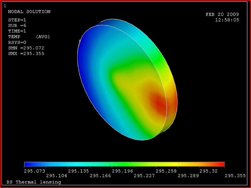
So the BS is heated by the heat radiated by the CPs, the BS RM might mitigate this effect. Anyway, I wanted to see if thi is an issue or not in terms of coupling losses.
The following pictures show the OPL increases from the various sources: TM heated by the YAG and RH, CP heated by the CO2 and the BS heated by the YAG and by the heat from the CPs. Since the BS is at 45° wrt to the YAG beam, I calculated the OPL increase in the vertical (Y) and horizontal (X) directions. The Y direction is not affected by the heat oming from the CPs, only X is.
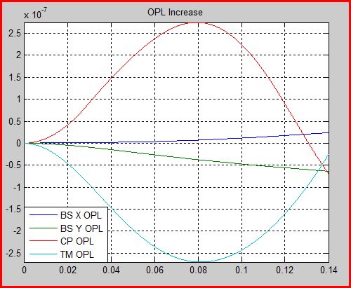
Next figure shows the residual OPL increase in the X and Y, sum of all contributions.
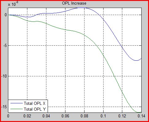
Corresponding coupling losses are 600ppm in X and 3000ppm in Y (but this could be decreased by applying a little bit more of CO2 power on the CPs). I think this is a strong support to the idea of suspending the CPs from the BS tower.
The BS is heated by the IFO beam, while the CPs are heated by the CO2 laser with a power equal to 4.5W, which is giving the nice 540ppm losses. Next figure shows the temperature map of the BS.
So the BS is heated by the heat radiated by the CPs, the BS RM might mitigate this effect. Anyway, I wanted to see if thi is an issue or not in terms of coupling losses.
The following pictures show the OPL increases from the various sources: TM heated by the YAG and RH, CP heated by the CO2 and the BS heated by the YAG and by the heat from the CPs. Since the BS is at 45° wrt to the YAG beam, I calculated the OPL increase in the vertical (Y) and horizontal (X) directions. The Y direction is not affected by the heat oming from the CPs, only X is.
Next figure shows the residual OPL increase in the X and Y, sum of all contributions.
Corresponding coupling losses are 600ppm in X and 3000ppm in Y (but this could be decreased by applying a little bit more of CO2 power on the CPs). I think this is a strong support to the idea of suspending the CPs from the BS tower.
Alessio- Posts : 127
Join date : 2008-11-07
Age : 52
Location : Rome
Increased radial resolution
![]() Alessio Mon Feb 23, 2009 7:35 pm
Alessio Mon Feb 23, 2009 7:35 pm
Alessio wrote:It seems that with a CP 3.5cm thick, it is possible to reach coupling losses as low as 540ppm, astonishing! Next picture shows the usual Log(Losses) vs CO2 power and Rin
So I decided to increase the Rin resolution from 5mm to 1.25mm. In this case, keeping the same resolution on the CO2 power, the number of simulations increase from 280 to 1036! ANSYS took several hours to complete and Matlab took something like 40min to analyze the data. But the result is very good. Next picture is the same LogLosses map.
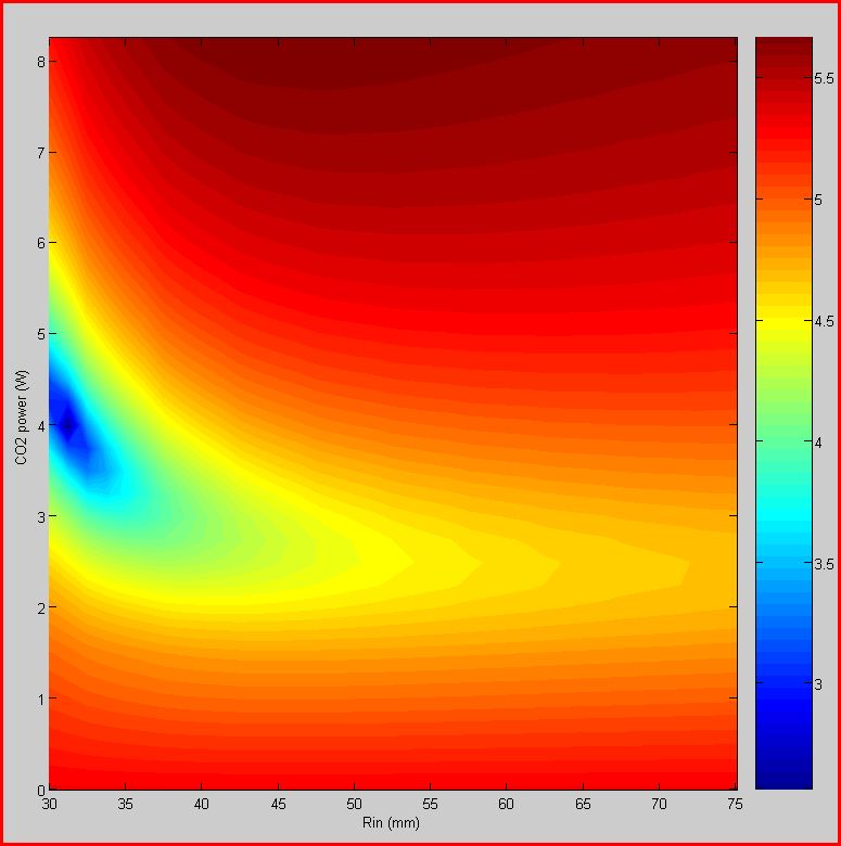
And this is the corresponding OPL for the lowest losses...
To make it short, we could get coupling losses as low as 300ppm!
Alessio- Posts : 127
Join date : 2008-11-07
Age : 52
Location : Rome
BS effect included
![]() Alessio Tue Feb 24, 2009 7:47 pm
Alessio Tue Feb 24, 2009 7:47 pm
I simply included the effect of the BS on the overall performances of the TCS. As in the previous calculations including the BS, I show results for the X and Y directions.
Usual Log(L) map for the X direction.
Same map for the Y drection.
Average of the two maps.
Results:
Usual Log(L) map for the X direction.
Same map for the Y drection.
Average of the two maps.
Results:
| Coupling Losses (ppm) | |
| X direction | 330 |
| Y direction | 740 |
| Average | 1630 |
Alessio- Posts : 127
Join date : 2008-11-07
Age : 52
Location : Rome
Page 1 of 1
Permissions in this forum:
You cannot reply to topics in this forum|
|
|