The SHACK-HARTMAN SENSOR as wavefront sensor
Page 1 of 1

The SHACK-HARTMAN SENSOR as wavefront sensor
![]() laura Thu Mar 18, 2010 12:41 pm
laura Thu Mar 18, 2010 12:41 pm
(Laura, Alessio)
During the last week of February we have been using for the first time the SHACK-HARTMAN SENSOR as wavefront sensor, on the system showed in fig.1.

Here lambda/4 was rotated to minimize the intensity of the reflected beam because the sensor (which is very sensitive) was close to the saturation.
The plate (and a beam combiner not present in the pictur, between the plate and the S.-H- sensor) had the aim to attenuate the beam entering the sensor.
To avoid the saturation effects we chose the third order beam produced by the reflection on the two faces of the plate.
Saturation effects on the sensor may be also controlled acting on the focusing device of the beam expander.
Infact we noted that a more large beam didn't saturate the sensor with respect to the same beam close to a smaller surface.
In fig.2 there is a typical image produced by the sensor. We can obtain via software all the correction due to the aberration and have a correct representation of the wavefront.
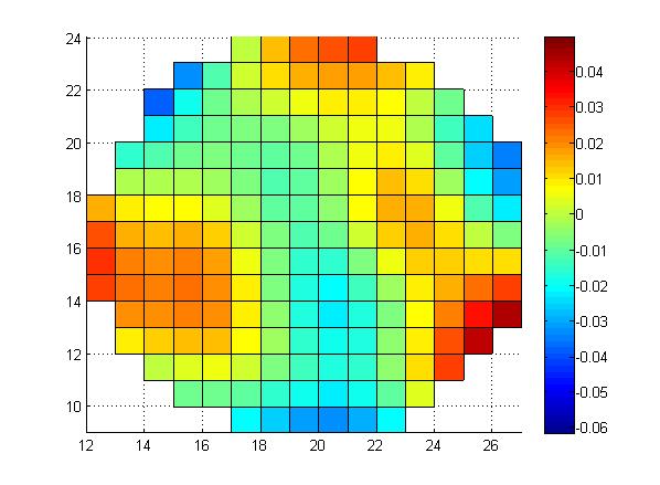
A correct way to use the sensor is to make a reference measurement in a standard situation and then to compare it whit other measurements obtained varying the initial system.
This is what we will make to verify the thermal lensing effects on the distorsion of the wavefront.
During the last week of February we have been using for the first time the SHACK-HARTMAN SENSOR as wavefront sensor, on the system showed in fig.1.
Here lambda/4 was rotated to minimize the intensity of the reflected beam because the sensor (which is very sensitive) was close to the saturation.
The plate (and a beam combiner not present in the pictur, between the plate and the S.-H- sensor) had the aim to attenuate the beam entering the sensor.
To avoid the saturation effects we chose the third order beam produced by the reflection on the two faces of the plate.
Saturation effects on the sensor may be also controlled acting on the focusing device of the beam expander.
Infact we noted that a more large beam didn't saturate the sensor with respect to the same beam close to a smaller surface.
In fig.2 there is a typical image produced by the sensor. We can obtain via software all the correction due to the aberration and have a correct representation of the wavefront.
A correct way to use the sensor is to make a reference measurement in a standard situation and then to compare it whit other measurements obtained varying the initial system.
This is what we will make to verify the thermal lensing effects on the distorsion of the wavefront.
laura- Posts : 8
Join date : 2009-11-05
Page 1 of 1
Permissions in this forum:
You cannot reply to topics in this forum